OBJECTIVES
The Localized Management of Sinus Floor is a surgical technique for transcrestal maxillary sinus floor elevation. Its aim is to create a surgical site for implants by displacing a portion of native residual below bone within the cavity of the maxillary sinus. This particular type of bone is usually found below the sinus floor and, through this technique, is displaced vertically in order to create a new implant alveolar portion. In the final configuration of the surgically created alveolus, the coronal portion of the crest must give primary implant stability. This will be completed by the coronal bone portion – pushed laterally and internally of the sinus cavity – from which, a sort of closed “tent” formed by the sinus membrane, will keep the cavity closed. The latter will be filled by blood produced by the alveolar walls.
Tissue repair of the peri-implant alveolus is totally entrusted to the physiological mechanism of bone repair on the site chosen for the implant osteotomy. 3-4-13-14
The goal is to change the height of available bone by creating an osteotomy tunnel starting from the crestal position and extending, initially transversally and medially, in a direction parallel to the palatine vault. This way, the osteotomy tunnel pushes the spongy bone against the floor of the maxillary sinus and avoids loss of the precious calcified structure.
The initially transverse direction (and not vertical, according to the normal prosthetic axis) is essential to:
1. Increase the height of native bone, interfacing the implant to improve primary stability;
2. Use the higher portion of the sinus floor which is normally found towards the medial side of the sinus cavity.
Preparation of the surgical field
According to the protocol, the preparation of the soft tissues is made with a partial thickness technique that has the objective to leave a thin layer of connective tissue which:
1. Ensures the integrity of the periosteum;
2. Allows to easily read the underlying bony anatomy.
The protection of the periosteum is critical, of course, to maintain the integrity of the blood supply15. Also the layer of connective tissue, and the interposed periosteum between tissue and bone, will be fundamental to promote the peri-implant tissue secondary intention healing. This is one of the main issues of the protocol.
This preparation enables to firmly anchor the keratinized tissue – using the sub-periosteal sutures – in an apical and vestibular position. This residual displaced tissue, previously covering the crest, has been displaced vestibularly14.
The flap preparation begins with a palatally beveled incision which slides along the bone plane, starting from the palatal angle of the crest, exactly where the palatal structure crosses the horizontal portion of the edentulous ridge. This has the aim of exposing the crest and displacing vestibularly the keratinized crestal residual tissue to the future implant emergency. This crestal tissue is the same one which has been previously moved from the palatal aspect of the surgical field. Fig. 01/05
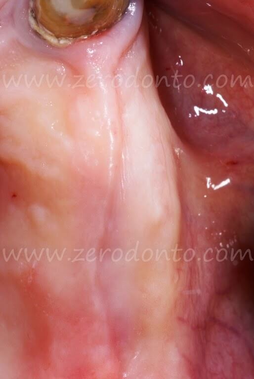
Fig. 01. Clinical aspect of the edentulous ridge of # 24 and # 25. The band of keratinized gingiva is now limited to the crestal position and the mucogingival line is now at the limit of the bucco-coronal angle.
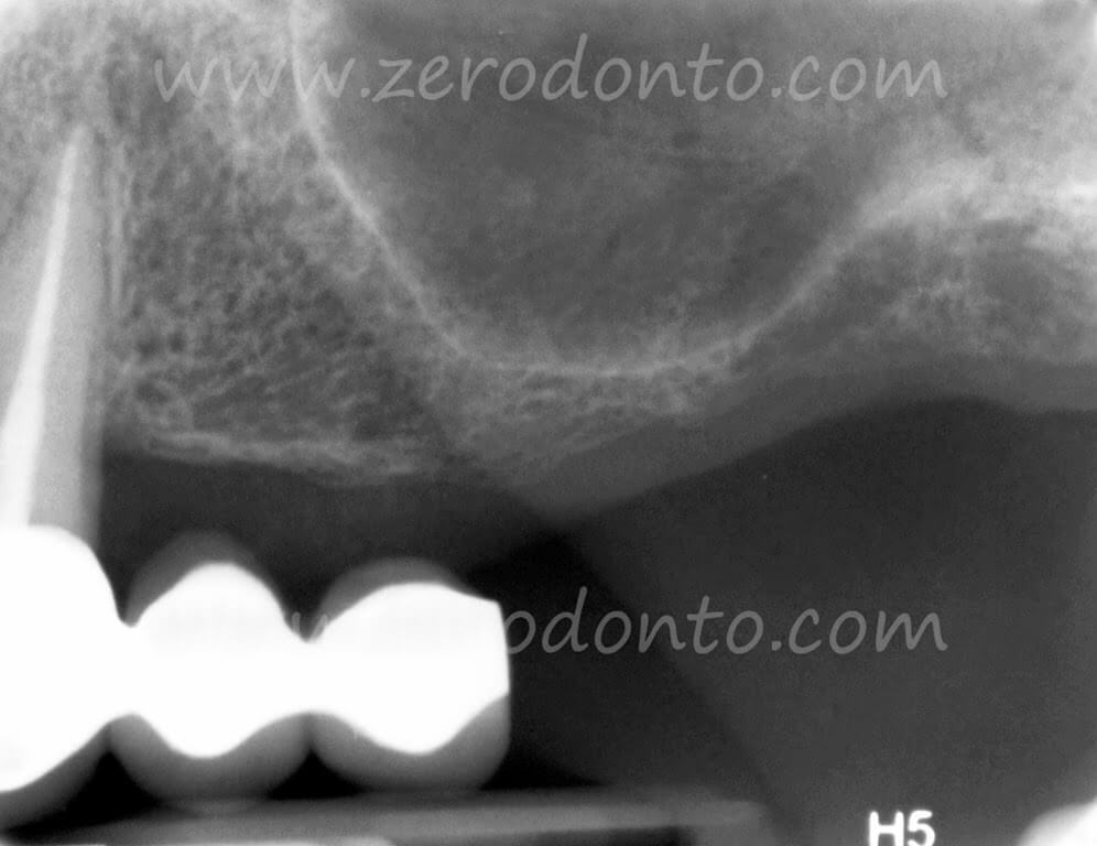
Fig. 02. Intraoral x-rays with the existing bridge and the descending position of the maxillary sinus floor. The latter greatly reduces crestal height in the anatomical position of # 25.
Less than 4mm height in section 17 of the Maxi-Scan Fig. 04a
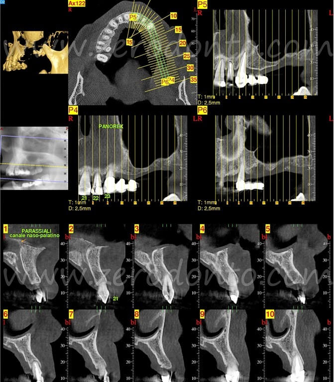
Fig. 03. Maxi Scan of the left maxilla from the palatal foramen to the distal portion of # 23.
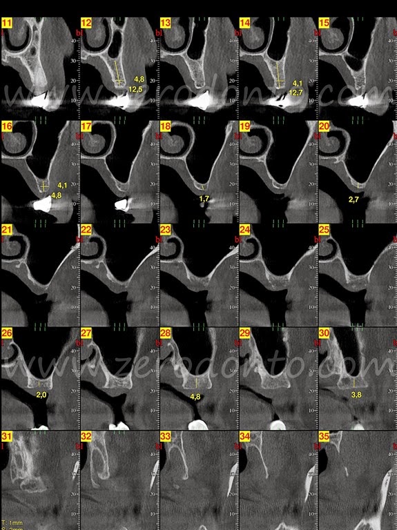
Fig. 04. Maxi Scan of the maxilla area from the left distal section at # 23. The sections involved in the insertion of the implants are the 12/13 for the implant in position # 24 and 15/16 for the implant in position # 25
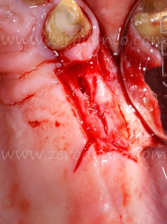
Fig. 05. The edentulous area was prepared according to the protocol described above, with a partial-thickness flap leaving a thin layer of connective tissue to ensure the periosteal continuity. The parasulcular incision of # 23 delimits the surgical field that can be used for the insertion of the implant and simultaneously maintains its anatomical integrity. An initial bone incision was carried out mesio-distally. The releasing palatal incisions are visible.
To overcome and loosen the muscle fibers over the muco-gingival line enables to completely release the flap.
The preparation on the buccal side of the flap is completed with parasulcular incisions around the adjacent natural teeth to delimit the osteotomy site and also to better mobilize the flap.
The second incision mirrors the first, starting on the palatal edge of the bevel, and continuing through the connective palatal tissue, always running the blade tip on the bone plane with a cut parallel to the profile of the palatal arch. This incision is necessary in order to underline the profile of the palatal curve. Fig. 05
When no adjacent natural teeth are present, elongated relaxing incisions are made always with a large base for the mucosal flap. 14 Fig. 05
Implant site preparation
The thrust of the dislocated spongy bone against the sinus floor creates fault lines of the dome that, simultaneously and gradually, push up the sinus membrane. 3/4/12/14
All this is possible with a sequence of instruments that do not have a cutting, but primary a pushing, capacity. Therefore the correct term for these instruments is “expanders”, rather than “osteotomes”.
The surgical protocol defines a specific set of instruments for the purpose. The first three instruments actually do have cutting capacity and are used with the aim of creating an initial crestal osteotomy where the prosthetic implant palatal emergency is planned. The palatal implant position remains the stable reference point as the bone flap will be distracted in a final buccal position.
This entry point into the bone structure may safely receive the second set of instruments (expanders) that, unlike the first, have rounded tips and are intended to displace the largest possible surface area of bone within the maxillary sinus in the medio-lateral direction. 3/14 Fig. 05
Contrary to the first, the second set of instruments have a rounded tip and have the aim of displacing the largest possible bone surface within the maxillary cavity in a medio-lateral direction.
Crestal bone that will be pushed inside the cavity to create the apical portion of the implant site. So as to say, the intra-sinus native bone alveolus structure that forms the apical portion of the new surgical bone socket. Fig. 06/010
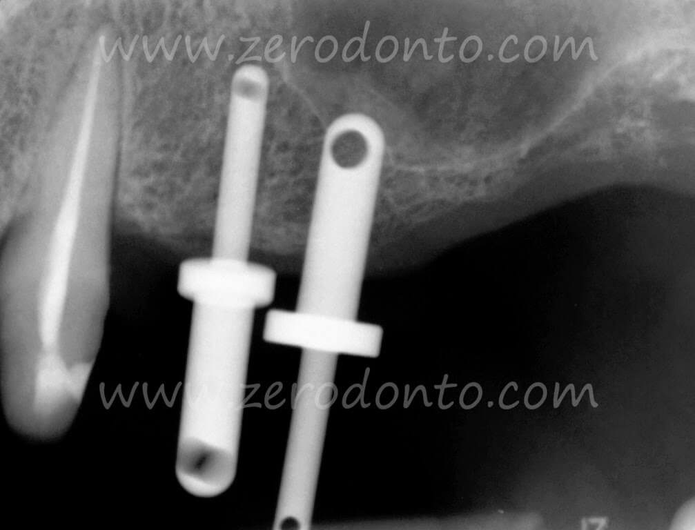
Fig. 06. Intraoperative x-rays with probes in position. The plate is 10mm thick. The first probe has a connective disk of 3.8mm diameter and the second of 4.7 mm. The second probe is inserted with the larger rounder 3mm tip which produced the first disruption of the sinus floor. It is clear that the space between the two initial surgical tunnels must be increased of at least 3mm. This can be done essentially mesializing the # 24 tunnel.
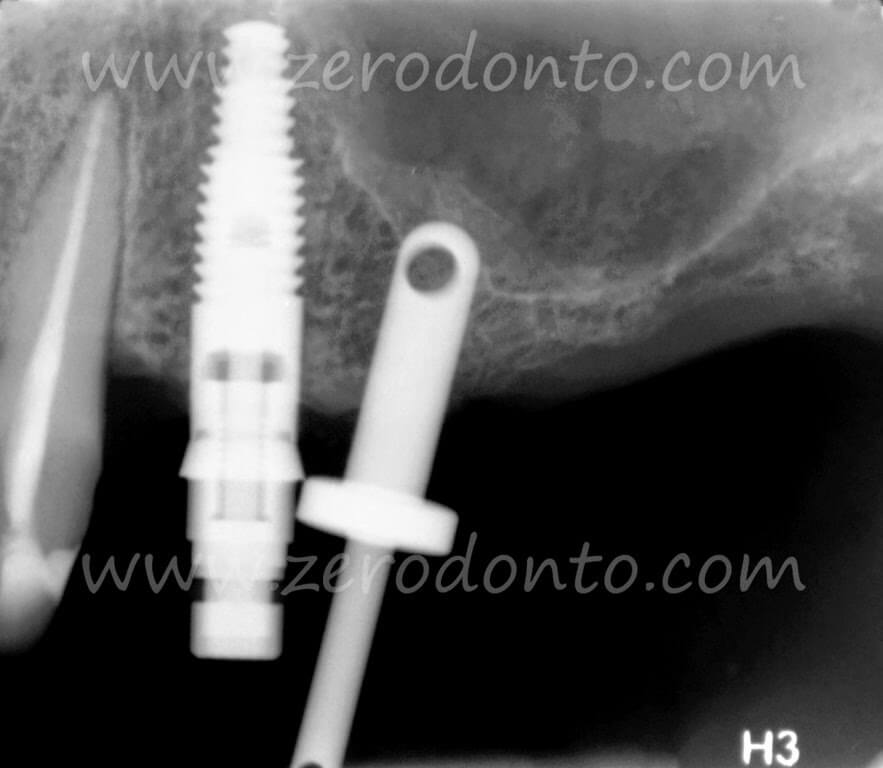
Fig. 07. The first implant of 3.8x13mm is almost in its final position. The second X-ray probe has been left in position so that it can be used as a stable reference point for defining the surgical site for the implant in position # 24.
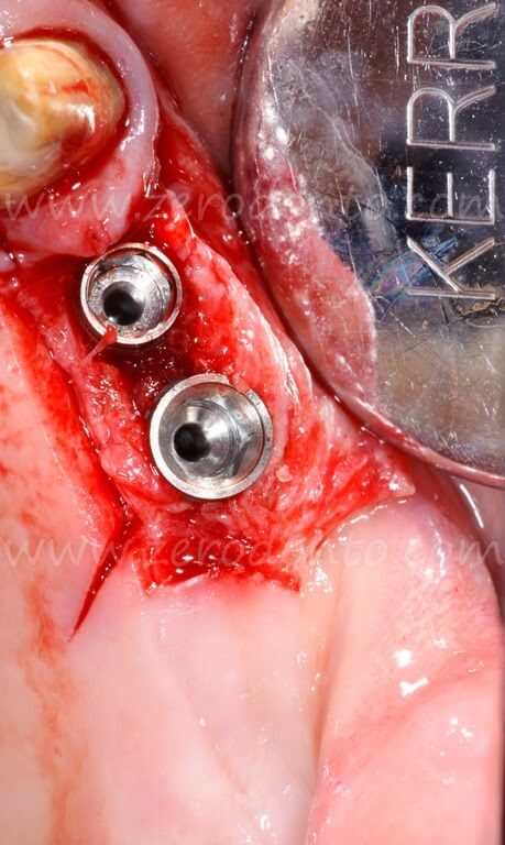
Fig. 08. Final position of the implants after removing the mounter. The implant in position # 24 is a 3.8x13mm and the implant in position # 25 is a 4.7×10.50mm. The amount of horizontal gain obtained by the combination of horizontal and vertical expansion is clearly visible.
The releasing bone incision comes from the inside of the first mesio-distal bone incision. It is beveled following the radial profile of the # 23 root prominence. This peculiar trace leaves the implant’s vestibular-mesial angle covered by the bone flap, thus maintaining the continuity of vascularization.
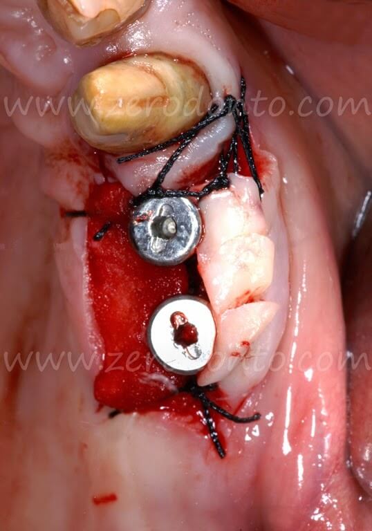
Fig. 09. The 2mm high healing screws have been tightened, as required by the protocol to 20 N/cm. It is essential to block a portion of collagen sponge under the palatal incision to prevent bleeding. The keratinized tissue taken from the palatal side of the incision has been adapted buccally to the screws and fixed in that position with subperiosteal sutures. This avoids excessive suture traction.
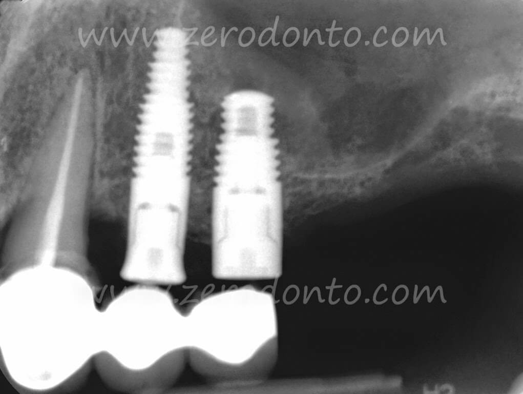
Fig. 010. Check X-ray with the healing screws and the cemented cantilever bridge. Excess cement under the bridge must be accurately removed. A portion of spongiosa displaced apically over the distal implant is clearly seen on the x-ray image. This creates a new peri-implant alveolus, displacing apically the native residual bone. This tissue was previously found lining the sinus floor.
The protocol does not require the use of burs.
The first cutting tool is the blade of the Beaver # 64 which will be used up to 1mm below the floor of the sinus. Fig. 05/06
After the Beaver # 64, two bone expanders with 90° cutting edges will be introduced in sequence:
1. the BE2 with the 1.5mm tip and, following, 2. the BE3 with the 1.9mm tip.
The BE2 and BE3 define a site for the emergence profile of the implant and an area of initial penetration that is used to guide the successive instruments with rounded tips8. The next bone expander is, in fact, the BE 45/15 with its 2.2mm rounded tip, which will be pushed below the floor of the sinus always transversally. The tunnel created with the BE 45/15 is then used to insert the 10mm length rounded 3mm diameter probe tip that will produce the first cracks in the medial side of sinus floor. Fig. 06/07
This probe will create a 10x3mm surgical tunnel parallel to the palatal vault. Reorientation towards the ideal (verticalized) prosthetic axis is obtained gradually when extracting this – and successive instruments – by forcing the tips of the instruments buccally during removal.
The following instruments, with a progressively increasing diameter, are inserted and then extracted with the same technique. It is very important that the final cavity must remain under dimensioned in both height and width, so that the final thrust is produced by the implant itself, which will be stabilized in the native bone available under the floor of the sinus. Fig 06/07
Before implant insertion, a portion of collagen is inserted and pushed using a Bone Expander in apical position, so that it remains interposed between the apex of the implant and the portion of displaced bone. This will create the apical, intra-sinus portion of the surgical alveolus5-10-11-12-14.
The extent of under sizing will be strictly conditioned by the quality of the bone and by the implant shape.
The changes induced in bone volume, are usually simultaneous to implant insertion.
The implant inserted into native bone will have the advantage of being functionalized at 70 days from insertion.
The reparative osteointegration can be easily followed-up with a clinical check and with a simple periapical x-rays7. Fig. 02/10/11/17/18
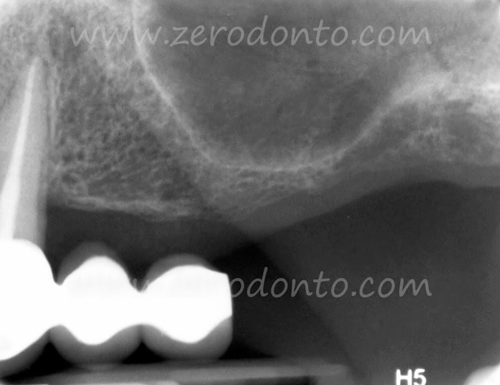
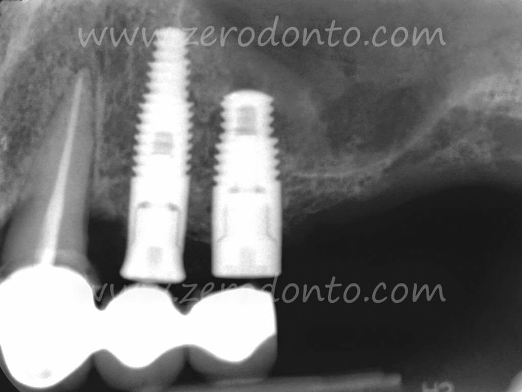
Fig. 010. Check X-ray with the healing screws and the cemented cantilever bridge. Excess cement under the bridge must be accurately removed. A portion of spongiosa displaced apically over the distal implant is clearly seen on the x-ray image. This creates a new peri-implant alveolus, displacing apically the native residual bone. This tissue was previously found lining the sinus floor.
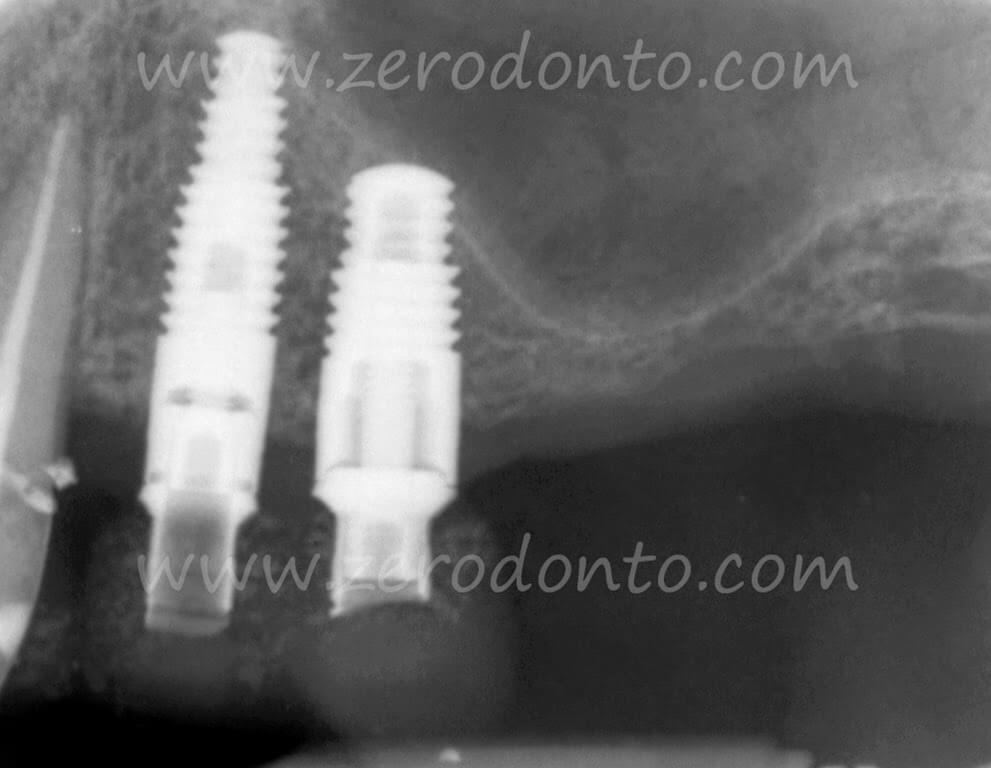
Fig 011. The check x-ray after three months of load shows new apical bone structures above the implants. A new cortical line delimits the new sinus floor position. This is a typical functional response to osseointegration.
The implants were loaded, according to protocol, with a functional provisional at about 70 days from insertion, for a period of three months.
Please note that no filler materials are used in the Localized Management of Sinus Floor technique.
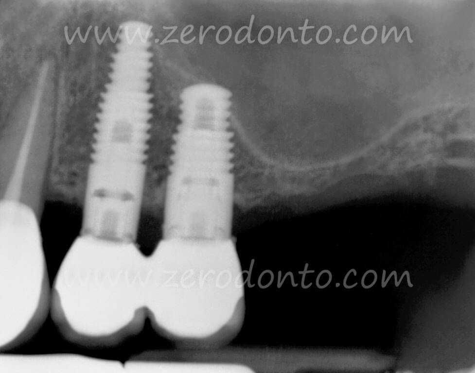
Fig. 017. Radiographic appearance two years after implant insertion and after about 18 months of functional load. In the image it is possible to read the new bone density at both the apical and coronal levels, due to the physiological response of the bone to the functional load.
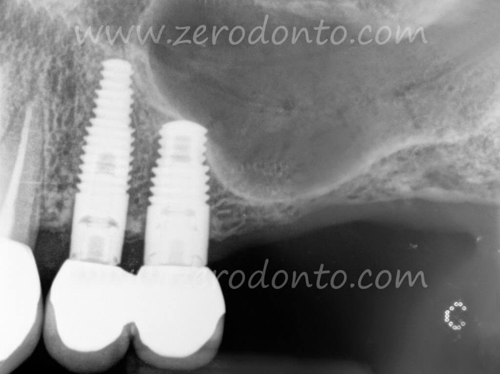
Fig. 018. X-ray situation at four years from implant insertion. Radiographycally it is possible to visualize the new bone density in the zone between #23 and #24. This is also possible in the inter-implant space and in the new cortical line that profiles the sinus cavity.
Apical repositioning and suturing of the flap
After implant insertion the surgical screws are tightened to 20 N/cm to test primary stability and prevent accidental screw loosening. Fig. 09/10
The flap is adapted buccally and compressed for a few seconds to the emergence profile of the healing abutment in order to stabilize it in its final position. This position must be maintained.
The flap is firmly fixed in the desired position with sutures anchored to the periosteum. Fig. 09
The suturing technique must prevent ischemia and tension in the repositioned soft tissues so that the blood flow is not obstructed. This is especially important in the phase in which the post-operative edema reaches its apex.
The choice of the height of the healing abutment is made according to the thickness of the soft tissue; the height must be sufficient to stabilize buccally the keratinized mucosa repositioned from the palate.
The gap that remains between the buccal and palatal edges of the flaps will heal by secondary intention. This will also favor the regeneration of peri-implant keratinized mucosa that, as such, will stabilize itself over time. Fig. 012/013/014/015
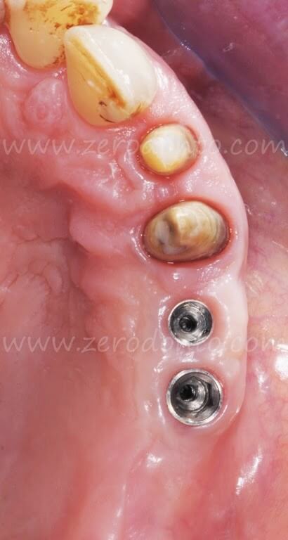
Fig. 012. Clinical appearance in an occlusal view at about a year after the insertion of the implants.
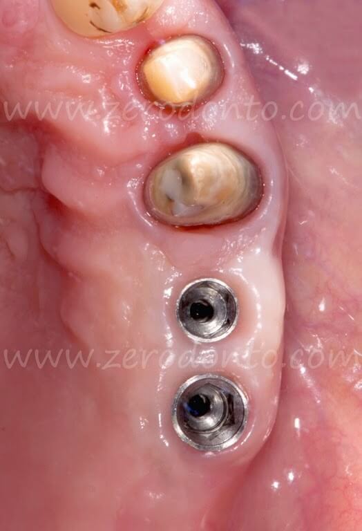
Fig. 013. Enlarged view where we can note how the implant profile emergency lies within a volume of cheratinized tissue similar to the physiological one. The muco-gingival line is apically displaced in a position similar to that of the natural contiguous teeth.
The interproximal gingival space between # 23 e # 24, where a deep post-surgical depression was present, has been practically completely filled as a primary result of the secondary intention healing. Compare to Fig. 09a
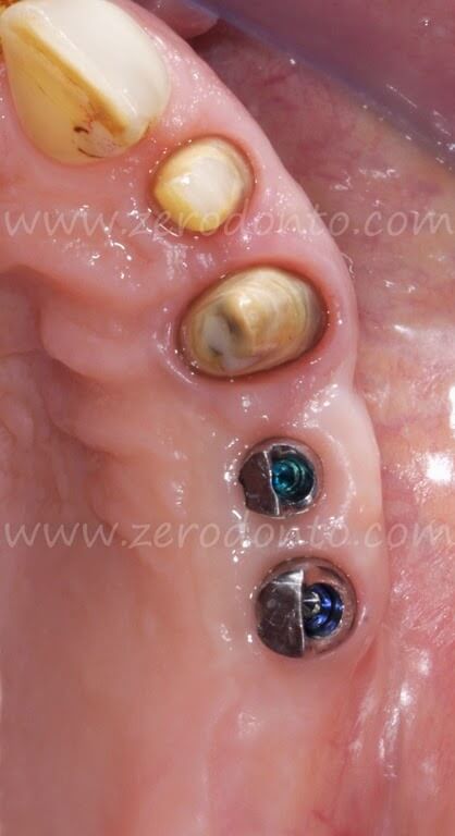
Fig. 014. Occlusal view with the implant abutments modified according to the Anatomically Modified Abutment (A.M.A.) technique before cementation of the final prosthesis.
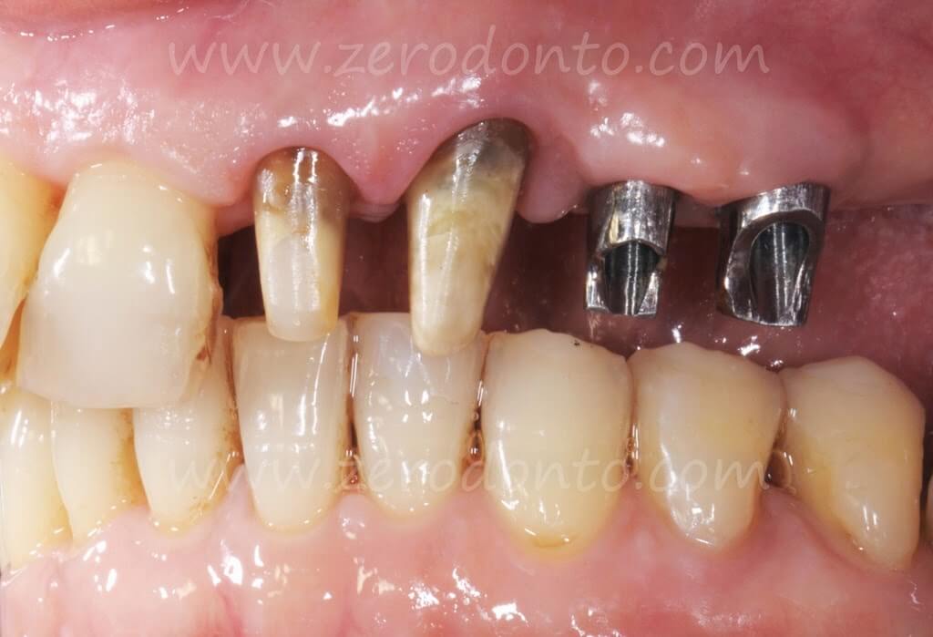
Fig. 015. Vestibular view with the A.M.A abutments ready for cementation.
Objectives of the flap technique
- To adapt the keratinized tissue present on the crest to the implant emergence profile.
- To increase the thickness and height of the keratinized tissue during implant insertion by avoiding a second surgical stage and probably establishing immediately the peri-implant biological width1-2-6-9.
- To reduce the surgical trauma and simultaneously re-establish a normal depth of the fornix.
- To preserve the natural anatomy of the contiguous teeth avoiding damage to the profile of the papillae.
- To mimic the natural morphology of the gingiva. Fig. 013/014/15/16
- To better cover the grey color titanium with thicker keratinized mucosa.
- To facilitate a more effective home care.
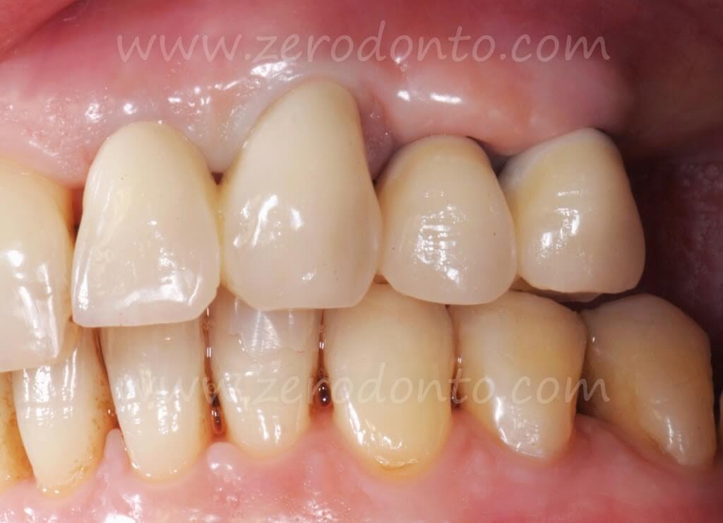
Fig. 016. Final crowns in position. The inter-papillar spaces are designed with an ideal emergency so as to enable the gum to adapt itself to the profile of the crowns.
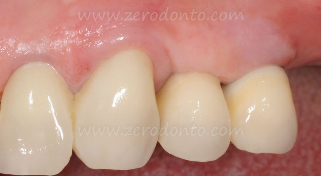
Fig. 017. 4 yrs follow-up.
References
Journals
1. Abrahamsson I, Berglundh T, Lindhe J . “The mucosal barrier following abutment dis/reconnection. An experimental study in dogs”, J Clin Periodont 1997;24 (8) : 568-72
2. Berlundh T, Lindhe J. “Dimension of the periimplant mucosa. Biological width revisited. J Clin Periodontol”, 1996 Oct;23(10):971-3
3. Bruschi GB, Scipioni A, Calesini G, Bruschi E. “Localized Management of Sinus Floor with Simultaneous Implant Placement. A Clinical Report”, Int J Oral Maxillofac Implants 1998;13:219-226
4. Bruschi GB, Crespi R, Capparè P, Bravi F, Bruschi E, Gherlone E. “Localized Management of Sinus Floor Technique for Implant Placement in Fresh Molar Sockets”, Clin. Implant Dent Relat Res. 2011 May 20
5. Buchter A, Kleinheinz J, Wiesmann HP et al. “Biological and Biomechanical evaluation of bone remodeling and implant stability after using an osteotome technique”, Clin. Oral Impl. Res. 16,2005; 1-8
6. Cocharan DL, Hermann JS, Schenk RK, Higginbottom FL, Buser D. “Biologic Width around Titanium Implant. A Histometric Analisis of the Implanto-gingival Junction around Unloaded and Loaded Nonsubmerged Impants in the Canine Mandible”, J Periodontol 1997 Feb; 68(2): 186-98
7. Friberg B. “A Comparison between Cutting Torque and Reasonance frequency measurements of maxillary implants. A 20-month Clinical Study”, Int J Oral Maxillofac Surg 1999 Aug; 28 (4):297-303
8. Hartmann GA, Cocharan DL, “Initial implant position determines the magnitude of crestal bone remodeling”, J Periodontol 2004; 75: 572-577
9. Linkevicius T. Apse P, Grybauskas S, Puisys A, “Influence of Thin Mucosal Tissues on Crestal Bone Stability around Implants with Platform Switching: A 1-year Pilot Study”, J Oral Maxillofac Surg 2010 Sep;68(9): 2272-7
10. Nkenke E, Kloss F, et al, “Histomorpfhometric and fluorescence microscopic analysis of bone remodeling after installation of implants using an osteotome technique”, Clin. Oral Impl. Res. 13, 2002; 595-602
11. Nobrega AR, Norton A, Siva JA, Silva JPD, Branco FM, Anitua E, “The osteotome Versus Conventional Drilling Technique for Implant Site Preparation: A Comparative Study in The Rabbit”, Int J Periodontics Rest 2013;32:e109-e115
12. Yilmaz HG, TÖzÜm TF, “Are Gingival Phenotype, Residual Ridge Height, and Membrane Thickness Critical for the Perforation of Maxillary Sinus?”, J Periodontol 2012; 83:420-425
13. Terheyden H, Lang NP, Bierbaum S, Stadlinger B, “Osseointegration – communication of cells”, Clin. Oral Impl. Res. 23, 2012, 1127–1135 doi: 10.1111/j.1600-0501.2011.02327.x
Books??
14. Bruschi GB, Crespi R, “Tecniche di espansione ossea in chirurgia implantare”, Quintessenza Edizioni 2012
Contributions to books
15. Wthinson SW. Ten Cate (ed), “Oral Histology”, 4th Edition.
16. Bruschi GB, Scipioni A, “Alveolar augmentation: New application for impants”, In: Heimke G. (ed), “Osseointegrated Implants, Vol I”, Boca Raton, FL CRC Press, 1990;2:35-61
CURRICULUM VITAE
DR. GIOVANNI BATTISTA BRUSCHI
M.D. University of Rome, D.M.D. (specialty in Dentistry) University of Rome. Assistant Professor at Boston University School of Graduate Dentistry Department of Prosthodontics directed by Prof. Martignoni. He has published numerous scientific articles in both national and international peer-reviewed journals. He is co-author of the book “Implantologia Orale” (Ed. Martina, Bologna, Italy). Co-author of the book “Implantoprotesi il ripristino dell’omeostasi tramiti restaurazioni singole” (Ed. Martina, Bologna, Italy). Co-author of the book “Techniques of bone expansion in implant surgery” (Quintessence International). Private practice in Rome limited to Oral Surgery and particularly Implantology and Endodontic Surgery.
E-mail: gbbruschi@gmail.com
For info: zerodonto@gmail.com

