NEW CONTROLLED BONE EXPANSION TECHNIQUE: MULTI-DISCIPLINE CLINICAL CASE (SURGICAL AND ORTHODONTIC PART)
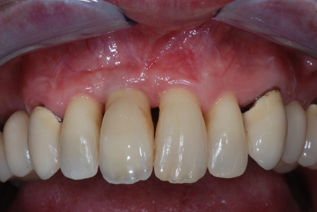
PROSTHESIC PHASE
In implant-prosthetic rehabilitation, the presence of horizontal or vertical bone re-absorptions represents one of the most frequent anatomic limits impeding implant positioning. When bone areas are not suitable for implant positioning, reconstruction techniques can be used to restore bone anatomy. These techniques allow implant inserting of appropriate number and length for a correct dental arch restore.
In case of severe horizontal crest atrophies, the technique used to restore a correct vestibular-oral dimension, are the following:
- regenerative techniques (Guided Bone Regeneration);
- bone grafts;
- expansion techniques;
- bone distraction;
- crest sagital osteothomy (ERE);
- extension Crest ;
- combined techniques (regenerative techniques, expansive techniques)
Edentulous bridge expansion (ERE) technique has been created in 1986 and presented 2 years later by Dr. Bruschi and Dr. Scipioni. The technique has been improved during the past years. Nowadays, it is used to reestablish orofacial dimensions suitable for alveolar atrophic crests during implant introduction without membrane induction and without bone-inductor or bone-conductor materials induction.
A study conducted on edentul sites treated with ERE technique confirmed that in the intraosseous rupture surgically created there is a complete bone regeneration. Interestingly, the same bone integration level is obtained on control sites treated with a traditional surgical implant technique. This technique uses the normal regenerative potential of the spongy bone, improved by a careful surgical approach with a periosteum conservation, together with recovery techniques by second intention. Intra-osseous rupture is, at first, filled by a clot; in the next days (about 40), there begins the formation of osteoid tissue that progressively (after 90-120 days) matures by increase in matrix mineralization and transformation of osteoblasts in osteocytes.
There are two principal prerequisites for bone regeneration after slit crest:
- a solid nutritional basis, with a minimum thickness of 1-1,5 mm of osseous flaps;
- an abundant blood flow necessary for newborn trabeculars.
This allows to avoid fenestrations, dehiscences or necrosis of vestibular osseous plate during the introduction and recovery phases of osteointegrated implants.
ERE technique is indicated in blade knife crests with a height of 10 mm minimum and a thickness of 4 mm minimum. It is performed by a crestal cut to release a flap of partial thickness edge in a vestibular and palatal direction. If necessary, two cuts are carried out in the mesial and distal limits of the surgical area. After the edges are raised, we proceed with cutting the bone in the crest center (5-7 mm deep); secondarily, we carry out two parallel trans-periosteal cuts. Thus, there result two vertical grooves in the vestibular cortical plan. A scalpel is inserted in the crest incision and beaten softly with a percussion hammer, until it reaches the lower part of the crack; at this point the scalpel will be used as a lever to dislocate the buccal plate in a vestibular direction.
The recovery period of implants inserted with the ERE technique is identical to the prescribed period for classic procedures. Nowadays, there seems to be a higher stability of the bone regenerated by bone expansion through time than that obtained by guided bone regeneration (GBR) techniques that tend to reabsorbed through time.
The disadvantage of the ERE technique is the risk of fracture of the vestibular wedge during the scalpel action, not being able to control the power during hammering. To avoid this risk the flap is cut at a partial thickness to guarantee blood flow of the cortical bone in case of fracture. On one hand the partial thickness flap preserves us from this risk, on the other hand not detaching the periosteum does not enable us to associate bone regeneration techniques.
Some years ago the Extension crest technique was presented.This technique, following incision in crest and bone expansion of 2 mm, is based on the insertion of a 2 mm thick distractor, activated by a screw and immediately bringing to the superior dental arch, or after a few days to the inferior arch to the crest expansion. This technique permits to control the expansion and to make it more predictable. A big disadvantage, instead, is the tool thickness. Actually, there exist 3 mm diameter implants of predictable use. Therefore, when the bone is expanded of 2 mm to introduce the Extension Crest there would be only 1 mm of expansion left for implant insertion. For all these reasons in the clinical practice during these last 4 years we tried to improve a controlled bone expansion technique that allows us to give predictability to the technique of bone expansion in order to obtain the detachment of a total thickness flap and so to associate guided osseous regeneration techniques.
The use of the scalpel cannot be foreseen and its’ power not being continuous may cause the fracture of the bone fragment with its consequent dislocation. Controlled osseous technique includes the use of manual screw expanders. Manual screw expanders can be checked more easily by the user, they allow to check with a ratcher its expansion power. In particular, they allow minimum expansion movements, each screw movement being of 0,2 mm. These screws should have a decreasing in its conical shape. This reduces expansion powers on the crest edge which is usually the weakest point.
Clinical case
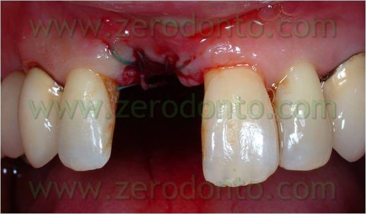
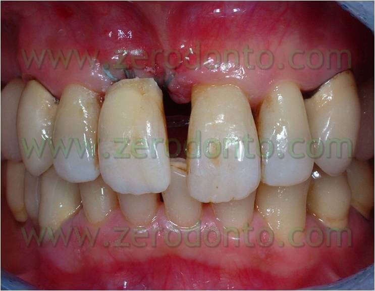
The patient of this case presented a medial survey until the apex of the element n.11 caused by a root fracture not immediately diagnosed and a 3 mm diasteme between the 2 superior central teeth. The extraction of this element was thus necessary as was the consequent implant rehabilitation following 9 months from the extraction. Meanwhile, it was necessary to put a temporary prosthesis on the edentule saddle and considering that the patient wanted to fill the space between the two central teeth it was also required an orthodontic movement to improve in a mesial-distal way the space for a future implant site and the prosthetic dental crown. The patient declined at the same time the multibrackets vestibular therapy which would have allowed at the same time the maintainance of the temporary tooth.


Orthodontic phase
Thus, we decided to make a lingual equipment, using an orthodontic wire bonded with a fluid composite, to carry out the movement and keep the temporary tooth. The tooth n.11 was extracted, a 16-16 iron wire was shaped in order to adapt itself passively to the lingual surface of the elements n.12 and n.13 and hence to have retentive handles for the temporary tooth. An interweaved passive wire for retainer with a thickness of 0.195 was shaped and applied on the lingual surfaces of the elements n. 21, n. 22, and n. 23. The temporary tooth was thus excavated at the level of the retentive handles of the wire. After bonding the iron 16-16 wire on the respective dental element the temporary tooth was bonded to the wire filling minuses earlier excavated with the fluid composite and positioning the temporary tooth in the handles of the wire (once found the precise position of the temporary tooth it could polymerize). The diasteme was closed with an elastic chain blocked by some ligatures between elements n.21-22 and 13-12. The chain was replaced every 3 weeks and the space filled in 12 weeks.
Once the space was filled, the chain was removed and a passive retainer was bonded on the lingual surface of the temporary tooth and element 21. This lingual device was kept until the implant was positioned. After 9 months from the extraction of the dental element, during implant insertion the passive retainer was removed between the temporary element, element 21, and the 16-16 wire which kept the temporary element (to bind them again after inserting the implant, to keep the temporary element and as a restraint for the filling of the space until the implant insertion).


Surgical phase
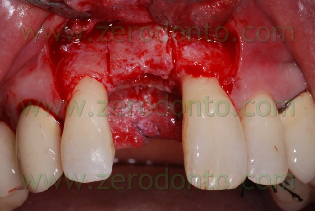
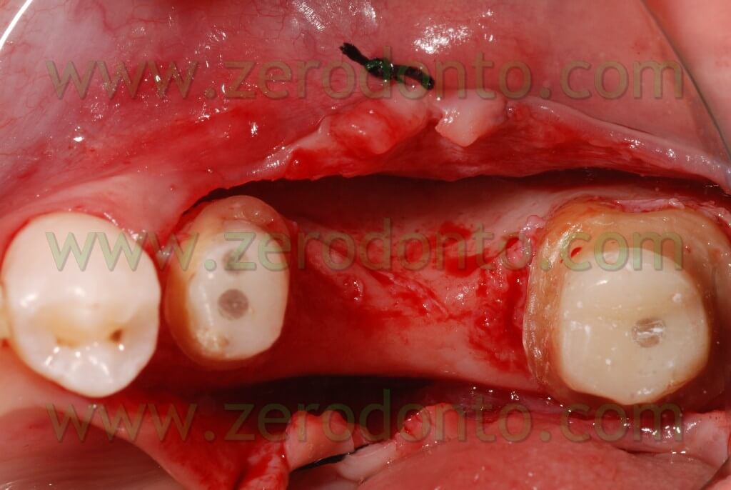
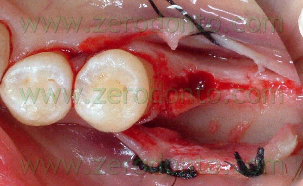
An intra-sulcular incision of a total thickness was carried out with two release distal cuts at n.12 and 21 as it was already decided to carry out reconstructive techniques to restore the horizontal deficit remainder after the extraction and restore the tissues’ convexity.


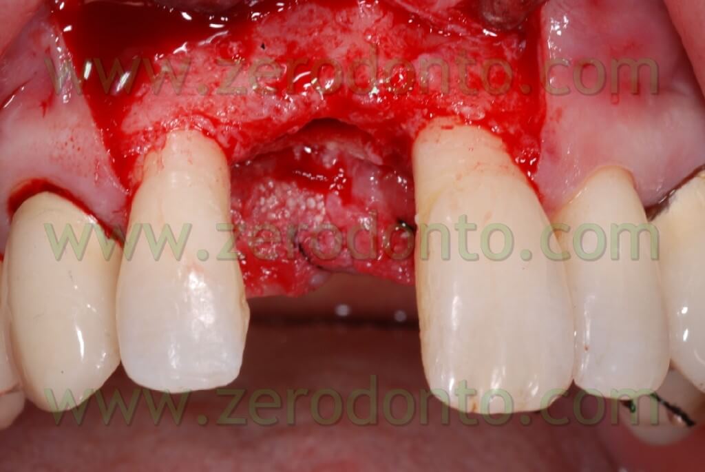

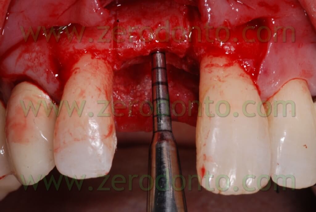
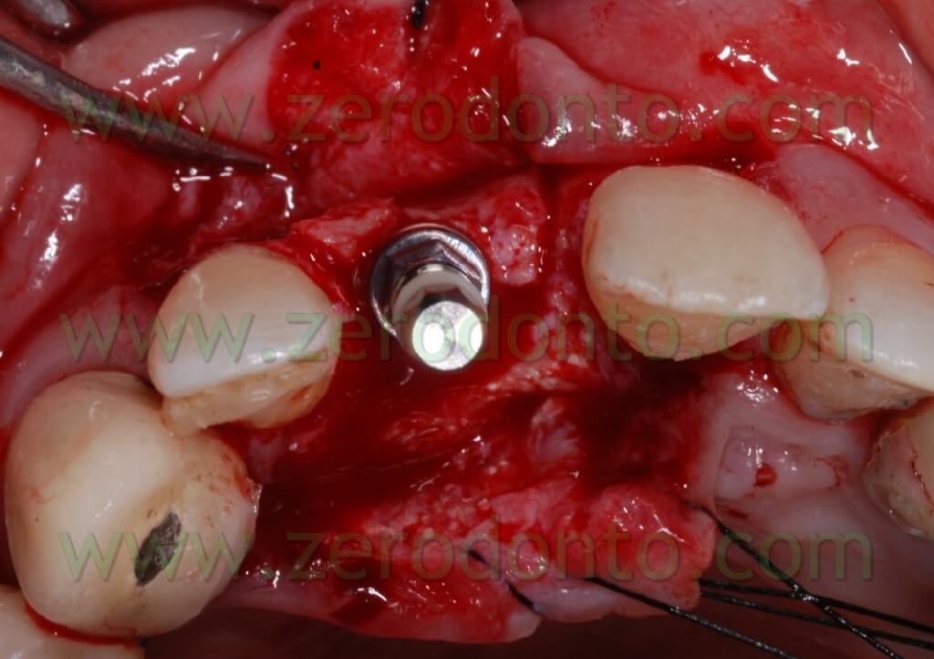
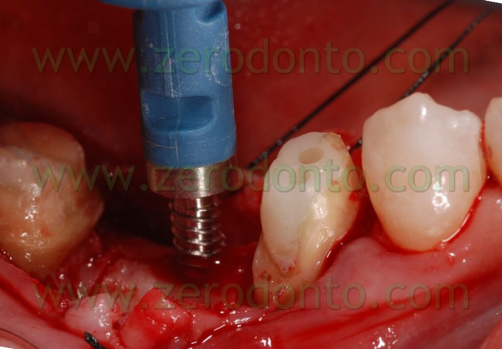
The bone site to distract was cut in the crest with a little disk with a diamond blade (Komet 943 ch.205 080), which worked slowly and under a rich spraying of physiological solution. Thereafter, two vertical bone incisions were carried out on the vestibular side which went to connect themselves to the first cut made at the center of the crest. In this way a vestibular bone wedge was delimited. It kept continuing connections with the bone in its apical position and along the vertical incisions. At this point, in order to create the path for the implant, there may be used both a mill with a reduced diameter and a manual acute expander, as in this case, with a reduced diameter.


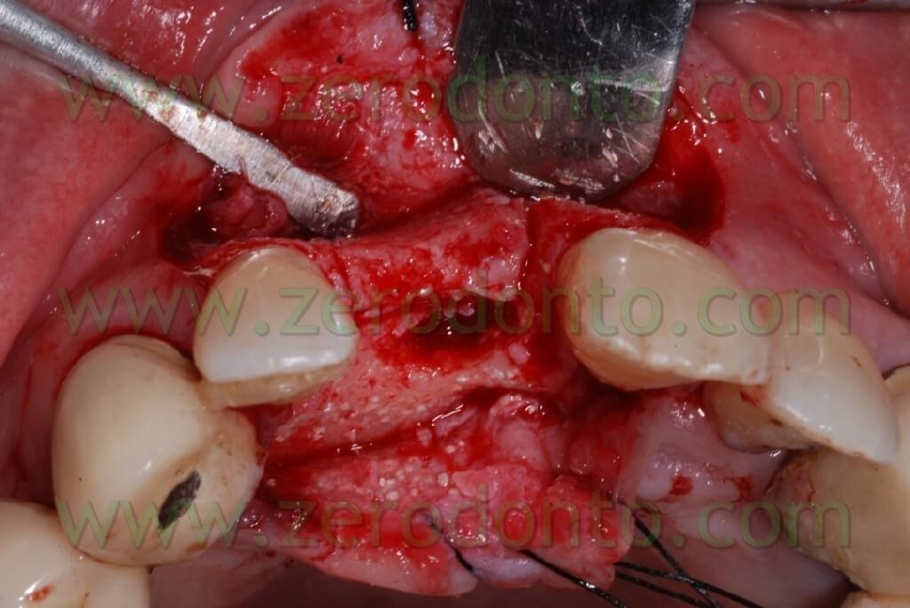
In the specific, it is a META expander with a diameter of 1,4 mm in the most coronal portion and with a diameter of about 1 mm if it is inserted for a depth of 10 mm.
In the future it could be ideal to have a screw expander with a cutting head. This could penetrate the bone in a controlled manner and be able also to control the inserting direction with a cricket.
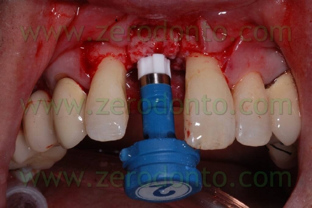
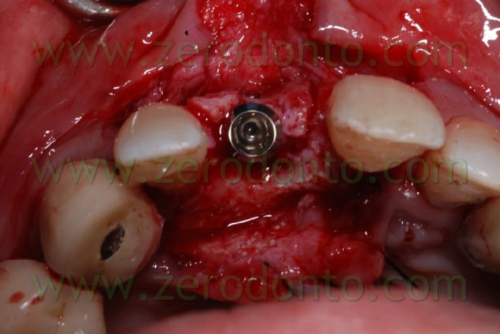
At this point, to dislocate the vestibular wedge we use screw expanders with a conical shape (we use in particular Ostwill’s compactors by Meta) which allow us to distract the wedge in an extremely controlled manner. These expanders are activated turning the screw slowly under irrigation of physiological solution until the bone doesn’t offer further resistance. After 20-30 seconds we screw again: periodical pauses are an intrinsic part of the surgical procedure which avails itself of the visco-elastic nature of the bone.
During these pauses, in fact, liquids, which are among the compressed trabeculas, leak out from the intra-trabecular spaces and this reduces the breaking risk of the vestibular area.
Each screwing corresponds to an expansion of about 0,2 mm. A dynanometric key allows us to check the resistance we meet, to measure the power, and to establish if it is necessary to wait some minutes to screw again.


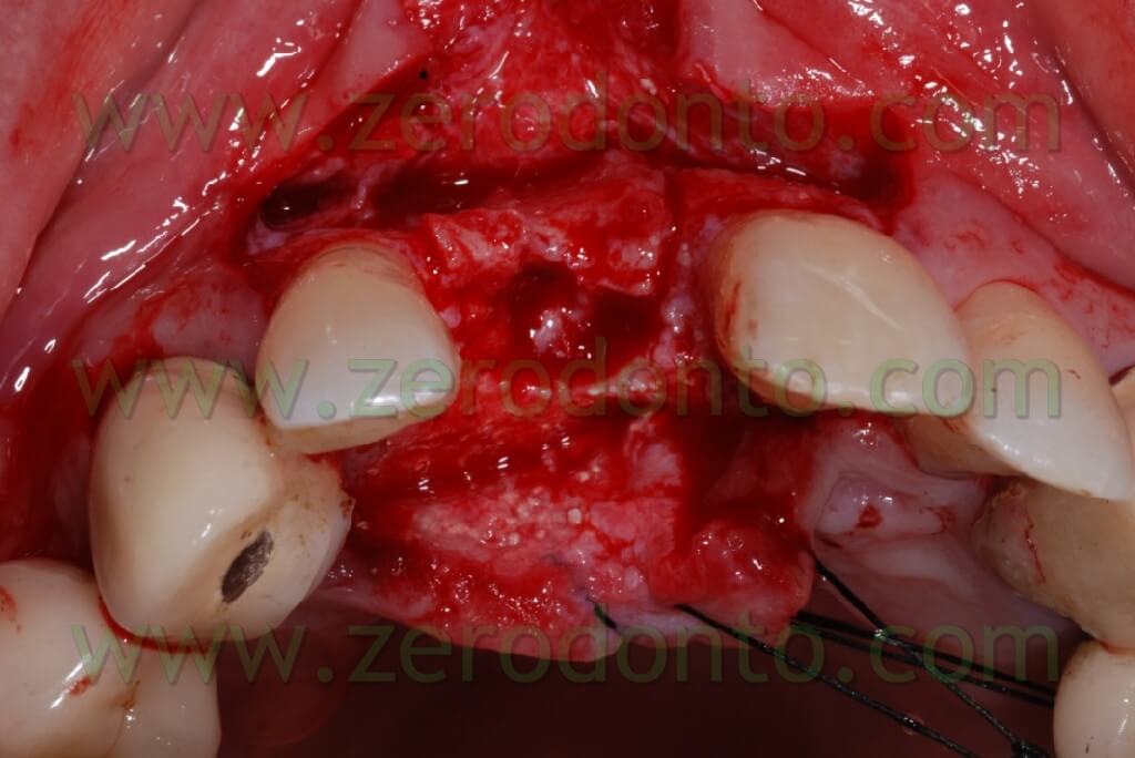
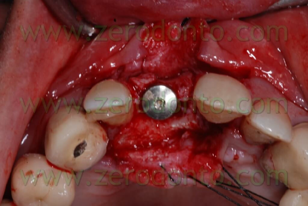
The clinical case here analyzed has been chosen for its technical complexity; in fact the presence of the nasal spine makes head to the expansion and moreover we have the possibility to associate a guided bone regeneration technique, which is not possible with the traditional ERE technique.
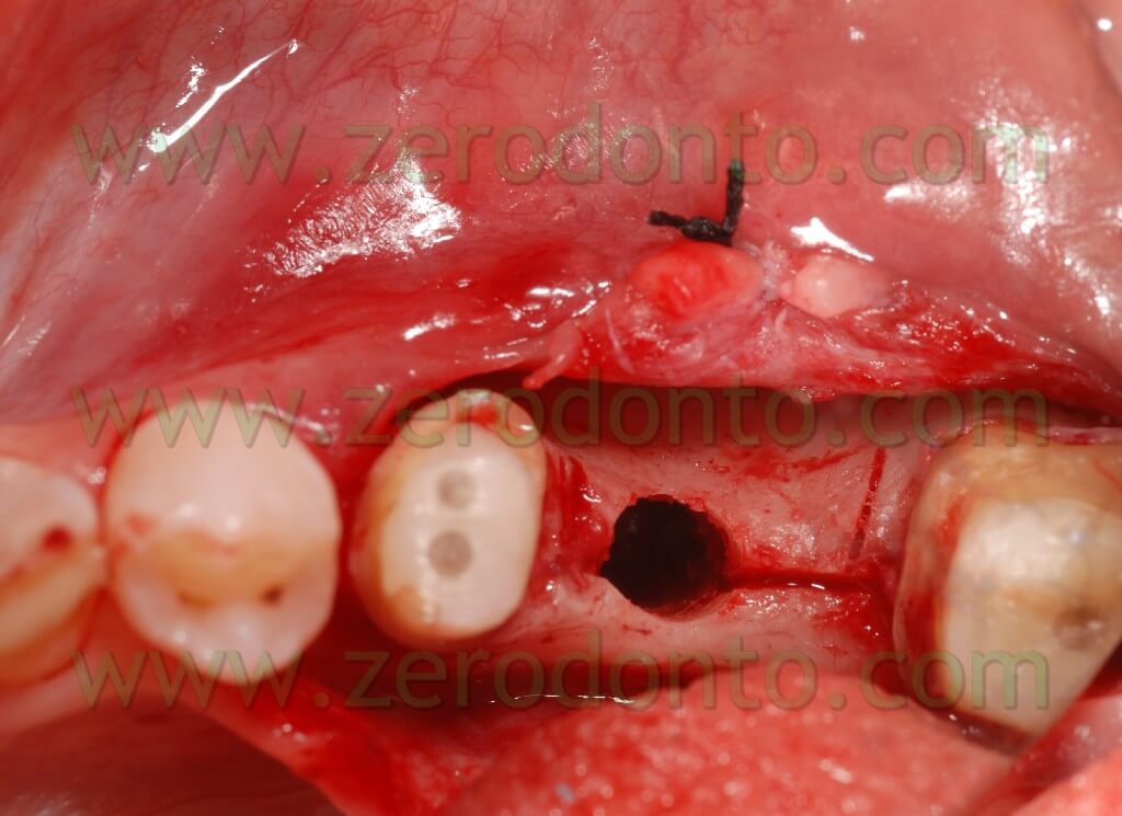
Such a case was inserted to show that there is the possibility to control the fragment fracture. In fact this has never occur in our clinical practice with this technique. In this case because the nasal spine made difficult the distraction it was not possible to obtain a perfect dislocation of the bone wedge. In fact, we obtain an expansion by a distal point of view; instead, by a mesial point of view an analogous wedge expansion didn’t occur, because of the higher osseous thickness, and above all because of the nasal spine. This caused a composed, filiform green wooden fracture vestibularly in the middle of the wedge itself. Almost certainly if we didn’t use screw expanders, with an expansion control, we would fracture irreparably the vestibular wedge without the possibility to introduce the implant. The showed breakage was a controlled cracking without loss of the fragment stability.

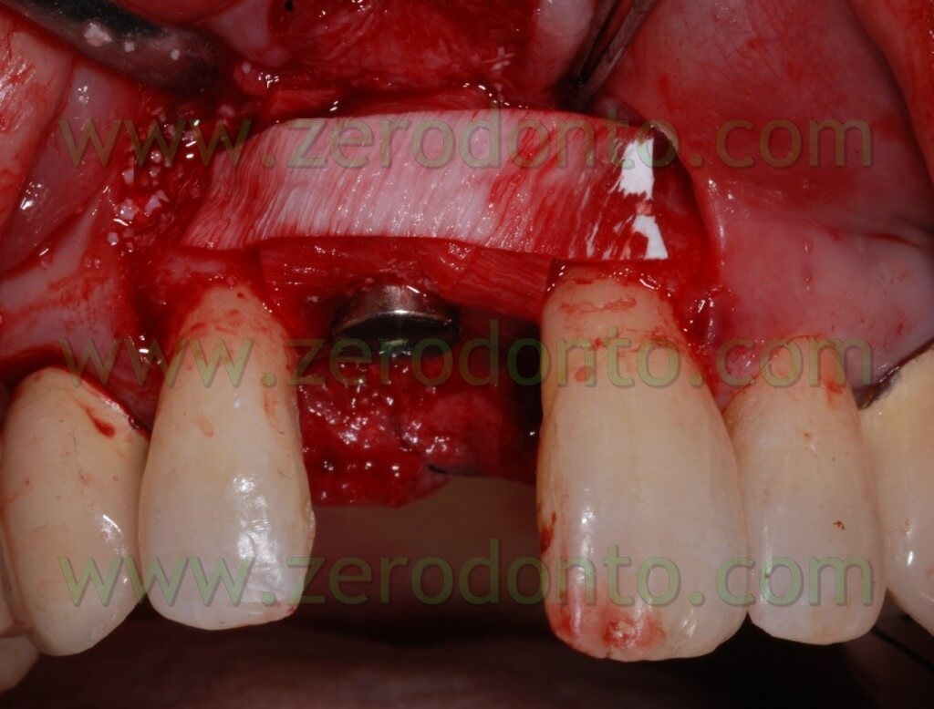
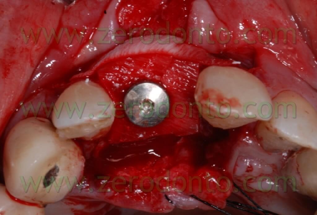
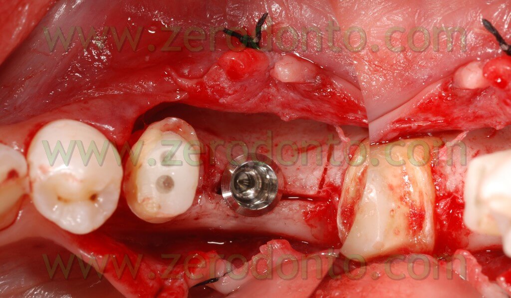
Once the area has been prepared, a 3,3 RN Straumann implant was inserted. It is long 10 mm with an innovative SLAactive surface, which needs 3 weeks to complete the implant osteointegration.


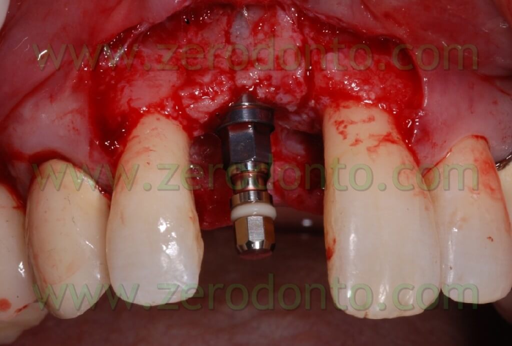
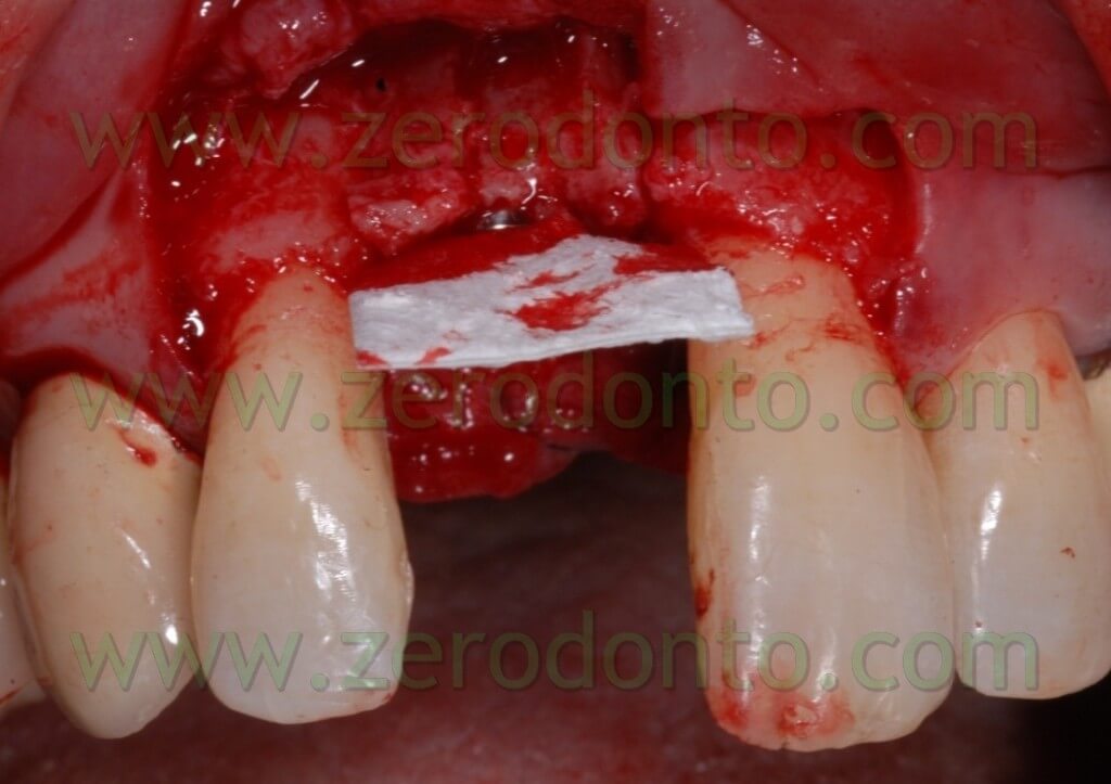
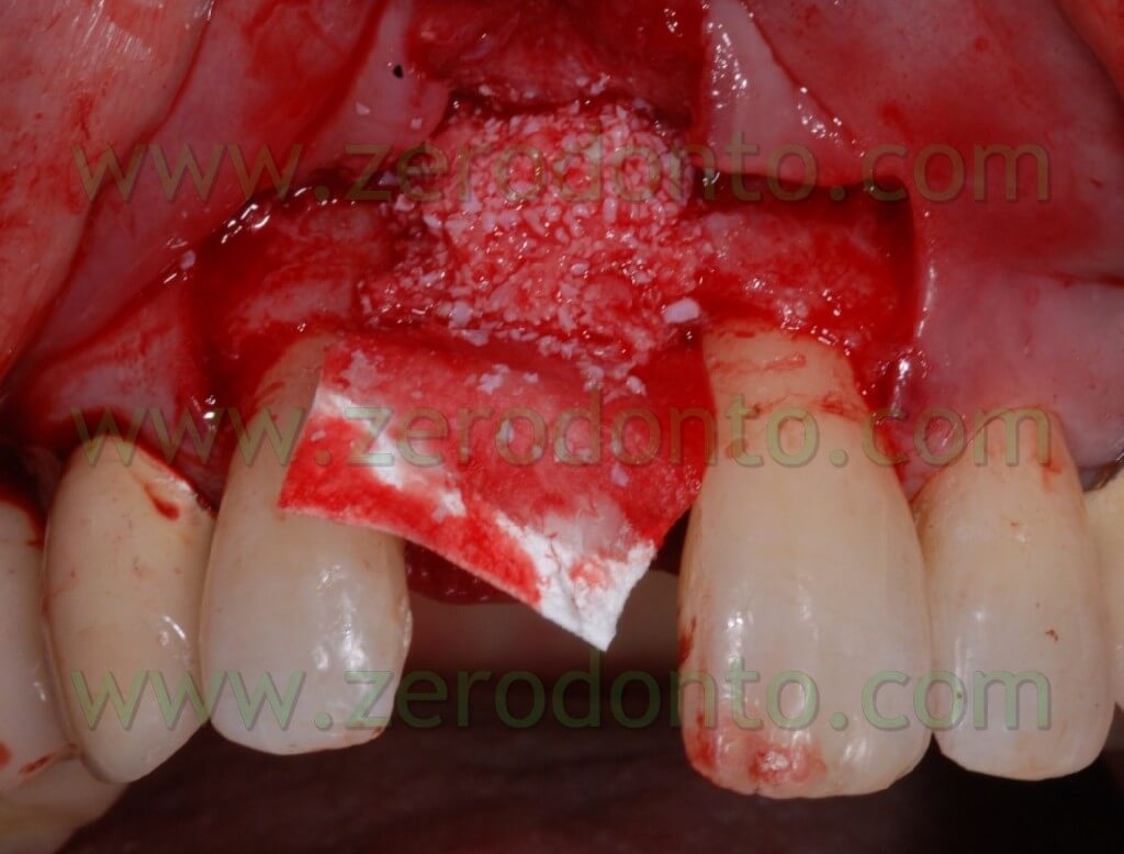
After completing fixture insertion, in order to ensure a restoration of the vestibular draft and to make stable the crest thickness, already cracked, there has been performed a Gbr technique vestibularly in respect to the implant.
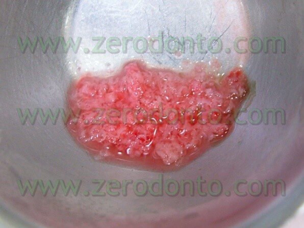
Particulate bone was picked up through a Micros scarping (Meta), obtained by the apical area of the implant place at the nasal spine level. This bone, mixed with Bio-oss at 50%, was applied on the vestibular side of the wedge and covered with a collagen reabsorbing Bio-gide membrane, anchored at the neck of the implant and blocked with other membrane” patches” in the apical area. In this way, we try to avoid all the possible micro movements that can bring to the GBR failure.


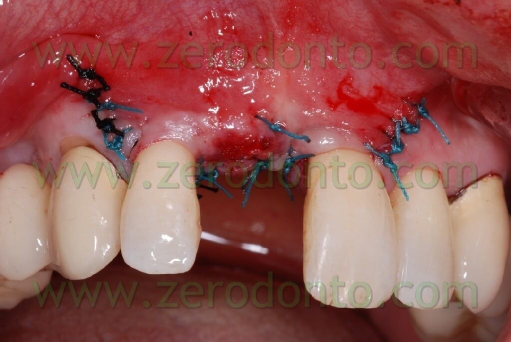
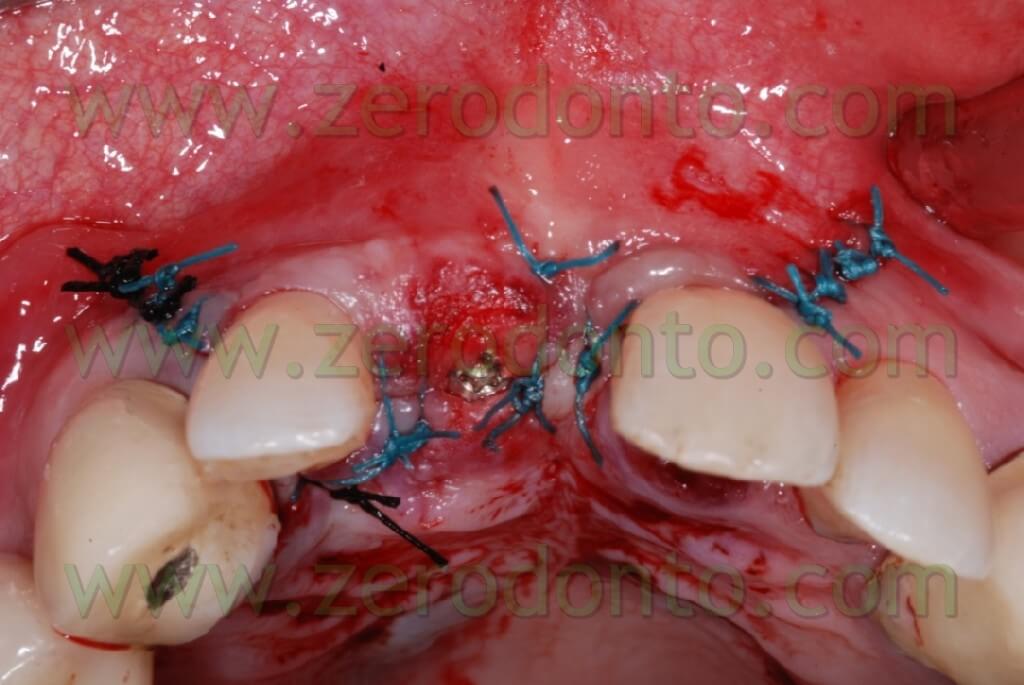
After performing an incision in the periosteum, to move the vestibular edge, we proceed to performed a suture to detached sutures in interweaved polyester covered by PTFE 4.0 n (Tevdek 4.0).
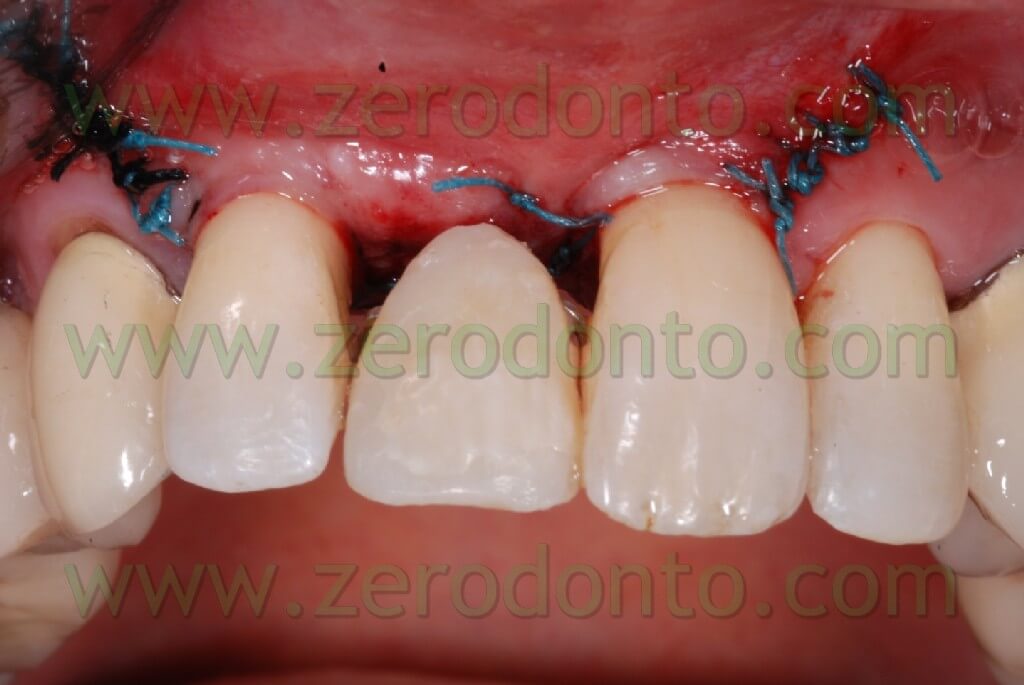


Here the PROSTHETIC FASE
Conclusions
This expansion technique, during the last 4 years, allowed us to control difficult expansions, inferior arch included, without fragment fractures.
The expansion control through the use of conical screws with a decreasing diameter allowed us to obtain big expansions in the inferior arch just with a release cut.
It is obvious that this is an experimental technique and therefore it needs to be further developed and tested with controlled studies and long term results.
References
Scipioni A, Bruschi GB.
Prosthetic solution on Frialit implants (Tübingen type).
Presented at the 4th International Congress of the Italian Academy of Prosthodontics, Padova, 4-6 October 1988.
Scipioni A, Bruschi GB, Calesini G.
The edentulous ridge expansion technique: a five-year study.
Int J Periodontics Restorative Dent. 1994 Oct;14(5):451-9.
Scipioni A, Bruschi GB, Calesini G, Bruschi E, De Martino C.
Bone regeneration in the edentulous ridge expansion technique: histologic and ultrastructural study of 20 clinical cases.
Int J Periodontics Restorative Dent. 1999 Jun;19(3):269-77.
Scipioni A, Bruschi GB, Giargia M, Berglundh T, Lindhe J.
Healing at implants with and without primary bone contact. An experimental study in dogs.
Clin Oral Implants Res. 1997 Feb;8(1):39-47.
Sethi A, Kaus T.
Maxillary ridge expansion with simultaneous implant placement: 5-year results of an ongoing clinical study.
Int J Oral Maxillofac Implants. 2000 Jul-Aug;15(4):491-9.
Peñarrocha M, Pérez H, Garciá A, Guarinos J.
Benign paroxysmal positional vertigo as a complication of osteotome expansion of the maxillary alveolar ridge.
J Oral Maxillofac Surg. 2001 Jan;59(1):106-7.
Chiapasco M, Ferrini F, Casentini P, Accardi S, Zaniboni M.
Dental implants placed in expanded narrow edentulous ridges with the Extension Crest device. A 1-3-year multicenter follow-up study.
Clin Oral Implants Res. 2006 Jun;17(3):265-72.
For further information:
zerodonto@gmail.com
